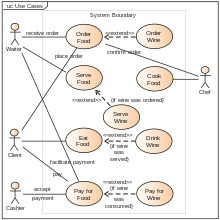
A UML use case diagram for the interaction of a client (the actor) within a restaurant (the system)
UML diagram types
Structural UML diagrams
Class diagram
Component diagram
Composite structure diagram
Deployment diagram
Object diagram
Package diagram
Profile diagram
Behavioral UML diagrams
Activity diagram
Communication diagram
Interaction overview diagram
Sequence diagram
State diagram
Timing diagram
Use case diagram
v
t
e
A use case diagram is a graphical depiction of a user's possible interactions with a system. A use case diagram shows various use cases and different types of users the system has and will often be accompanied by other types of diagrams as well. The use cases are represented by either circles or ellipses. The actors are often shown as stick figures.
UML diagrams such as activity diagrams, sequence diagrams, communication diagrams, and state machine diagrams can also be used to visualize usecases accordingly...
diagrams are typically associated with usecase realizations in the 4+1 architectural view model of the system under development. Sequence diagrams are...
sequenced messages. Communication diagrams represent a combination of information taken from Class, Sequence, and UseCaseDiagrams describing both the static...
A diagram is a symbolic representation of information using visualization techniques. Diagrams have been used since prehistoric times on walls of caves...
relationships among objects. The class diagram is the main building block of object-oriented modeling. It is used for general conceptual modeling of the...
engineering, most practitioners do not use UML, but instead produce informal hand drawn diagrams; these diagrams, however, often include elements from...
concurrency. However, the join and split symbols in activity diagrams only resolve this for simple cases. The meaning of the model is not clear when these symbols...
context diagram, a problem diagram shows requirements and requirements references. Usecasediagram: One of the Unified Modeling Language diagrams. They...
(UML), a component diagram depicts how components are wired together to form larger components or software systems. They are used to illustrate the structure...
case diagram. The model introduces 2 new important entities (in addition to those from the traditional usecase model, usecase and actor: Misuse case :...
abuse casediagrams. They are drawn with the same symbols as a usecasediagram. To distinguish between the two, the usecasediagram and abuse case diagrams...
A state diagram is used in computer science and related fields to describe the behavior of systems. State diagrams require that the system is composed...
diagrams have practical and theoretical applications in many fields, mainly in science and technology, but also in visual art. In the simplest case,...
(objects). Object diagrams are more concrete than class diagrams. They are often used to provide examples or act as test cases for class diagrams. Only aspects...
A deployment diagram in the Unified Modeling Language models the physical deployment of artifacts on nodes. To describe a web site, for example, a deployment...
diagram is a widely useddiagram style that shows the logical relation between sets, popularized by John Venn (1834–1923) in the 1880s. The diagrams are...
often used in analysis to represent an artifact or other item. Table: a stereotyped class. Package diagrams can use packages containing usecases to illustrate...
Ishikawa diagrams (also called fishbone diagrams, herringbone diagrams, cause-and-effect diagrams) are causal diagrams created by Kaoru Ishikawa that...
another set diagramming technique, Venn diagrams. Unlike Venn diagrams, which show all possible relations between different sets, the Euler diagram shows only...
Interaction Overview Diagram is one of the fourteen types of diagrams of the Unified Modeling Language (UML), which can picture a control flow with nodes...
In order theory, a Hasse diagram (/ˈhæsə/; German: [ˈhasə]) is a type of mathematical diagramused to represent a finite partially ordered set, in the...
Package diagram Parametric diagram Requirement diagram Sequence diagram State machine diagramUsecasediagram There are several modeling tool vendors offering...
physics and engineering, a free body diagram (FBD; also called a force diagram) is a graphical illustration used to visualize the applied forces, moments...
SysML entities: Usecase (in a usecasediagram) Action (in an activity diagram) State transition trigger (in a state machine diagram). As OPM and SysML...
 Global Information